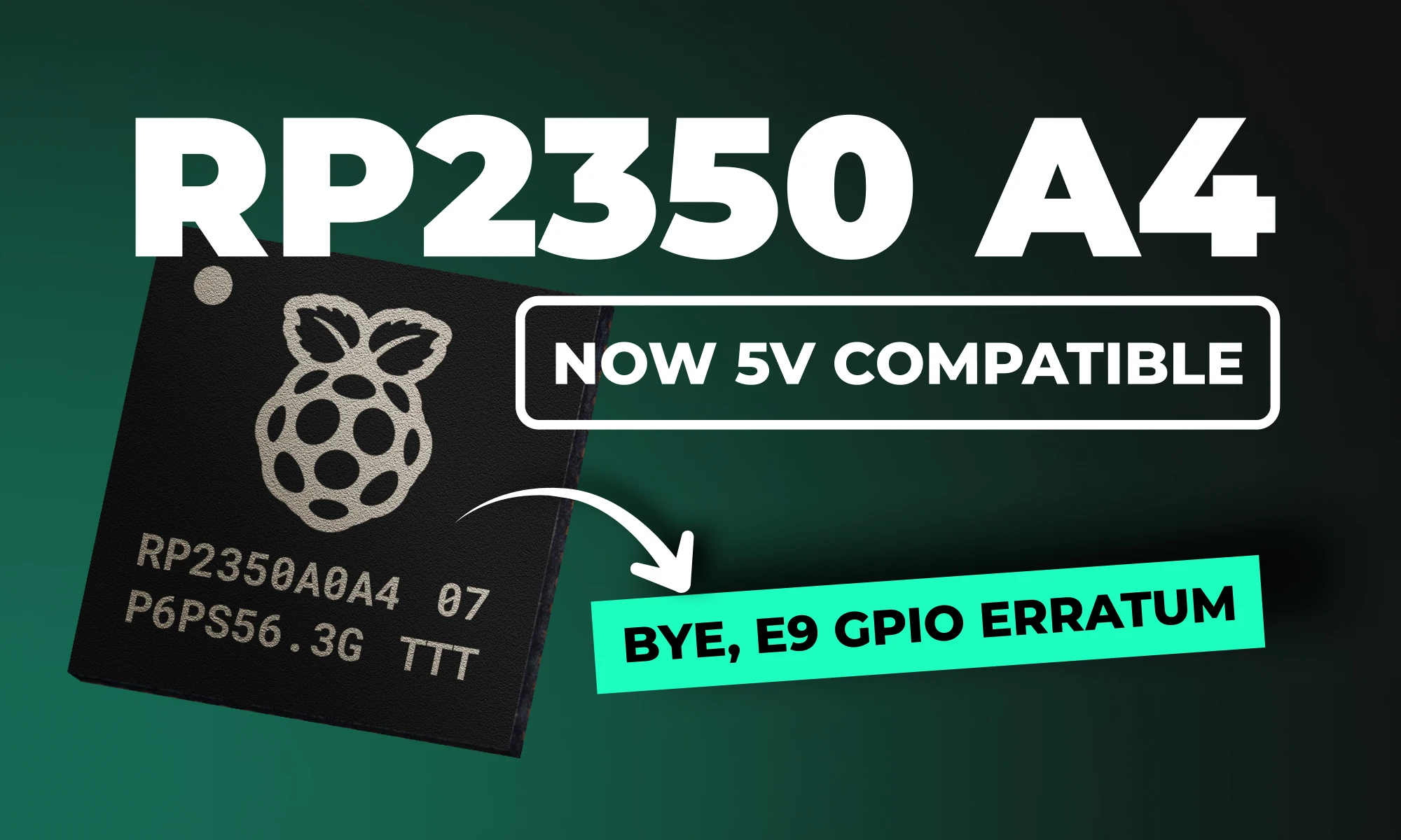
Raspberry Pi recently introduced the RP2350 A4 stepping, bringing critical enhancements to its flagship dual-core microcontroller. With security improvements, resolved hardware issues, and added features, the RP2350 A4 stepping isn't just another incremental update, it's transformative. But what exactly has changed, and how will it impact your Raspberry Pi Pico projects?
Let’s dive into the details.
What Is the RP2350 A4 Stepping?
The RP2350 A4 stepping is the latest iteration of Raspberry Pi's powerful dual-core MCU, designed to correct significant hardware and security issues identified in earlier versions (particularly the A2 stepping). This update provides comprehensive improvements, delivering both enhanced security and optimized hardware performance, making it a must-have upgrade for serious developers and embedded systems designers alike.
If you're connecting the RP2350 to retro computing hardware, there's good news: after extensive testing, the RP2350 is now officially 5V tolerant!
{{underline}}
Can My Current Pico Projects Run on the New A4 Stepping?
Absolutely! Because A4 is a pin-compatible, drop-in replacement, your existing Pico designs work right away, often with nothing more than a rebuild on the latest SDK. Here are four examples you can migrate today:
- Pico Smart Automation Controller – A DIY home-automation hub that enables intelligent control for sensors, relays, and devices.
- Pico Macro Keyboard – A customizable USB HID keypad a.k.a macro pad built using the Raspberry Pi Pico 2.
- Avocaudio – Tiny Community Audio Board – A tinyML board designed for extensive audio data collection across various tinyML applications.
- Raspberry Pi Pico 2 Shield Template – A ready-made “shield” PCB that mirrors the exact footprint and pin order of the Pico 2, much like an Arduino shield.
{{upsell-project}}
{{underline}}
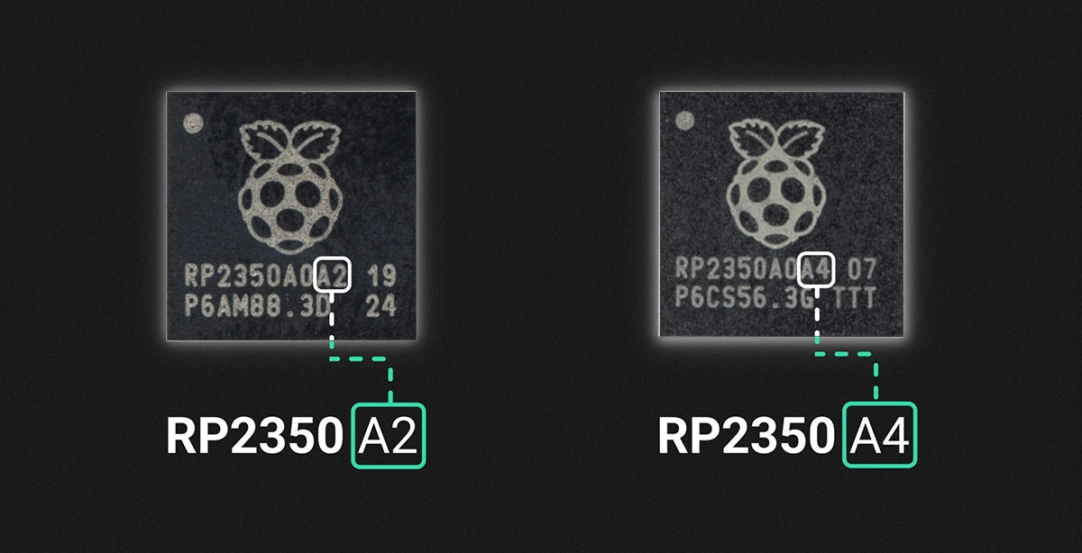
How Can I Tell If I Have the A2 or A4 Stepping?
You can identify the stepping version from the marking on the top surface of the chip, as illustrated below.
{{underline}}
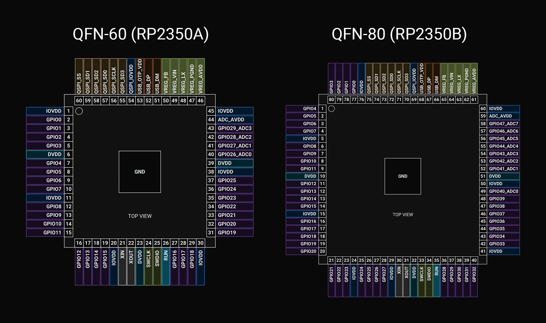
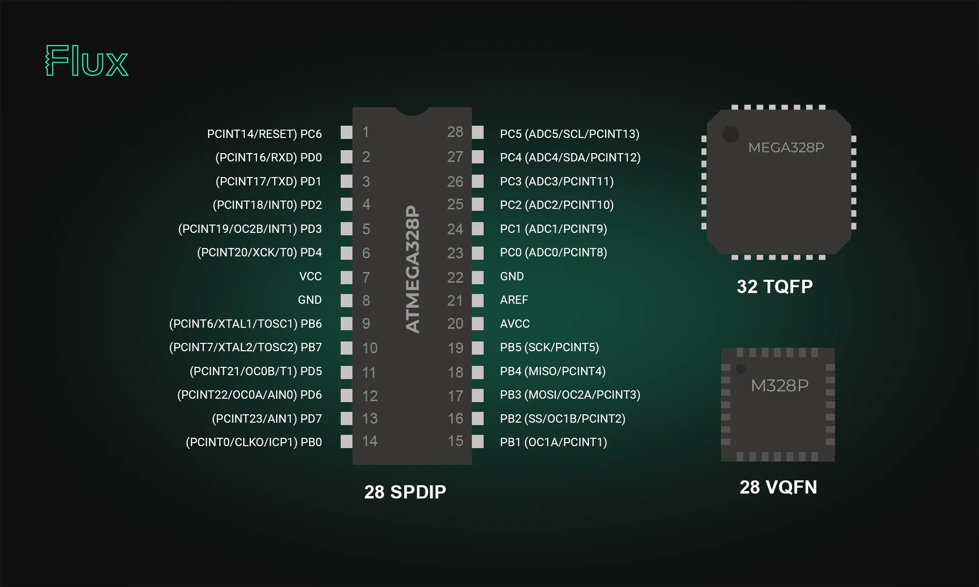
Do Pinouts Change with the RP2350 A4 Stepping?
No, great news for hardware engineers! The pin configuration and layout of the RP2350 A4 stepping remain identical to earlier versions, making it a perfect drop-in replacement. You can upgrade existing hardware designs without any modifications to your PCB layouts.
Below, I've included a detailed pinout mapping for quick reference.
GPIO Pins
| Name | QFN-60 | QFN-80 | Type | Power Domain | Description |
| :--- | :---: | :---: | :--- | :--- | :---: |
| GPIO0 | 2 | 77 | Digital IO (FT) | IOVDD | User IO |
| GPIO1 | 3 | 78 | Digital IO (FT) | IOVDD | User IO |
| GPIO2 | 4 | 79 | Digital IO (FT) | IOVDD | User IO |
| GPIO3 | 5 | 80 | Digital IO (FT) | IOVDD | User IO |
| GPIO4 | 7 | 1 | Digital IO (FT) | IOVDD | User IO |
| GPIO5 | 8 | 2 | Digital IO (FT) | IOVDD | User IO |
| GPIO6 | 9 | 3 | Digital IO (FT) | IOVDD | User IO |
| GPIO7 | 10 | 4 | Digital IO (FT) | IOVDD | User IO |
| GPIO8 | 12 | 6 | Digital IO (FT) | IOVDD | User IO |
| GPIO9 | 13 | 7 | Digital IO (FT) | IOVDD | User IO |
| GPIO10 | 14 | 8 | Digital IO (FT) | IOVDD | User IO |
| GPIO11 | 15 | 9 | Digital IO (FT) | IOVDD | User IO |
| GPIO12 | 16 | 11 | Digital IO (FT) | IOVDD | User IO |
| GPIO13 | 17 | 12 | Digital IO (FT) | IOVDD | User IO |
| GPIO14 | 18 | 13 | Digital IO (FT) | IOVDD | User IO |
| GPIO15 | 19 | 14 | Digital IO (FT) | IOVDD | User IO |
| GPIO16 | 27 | 16 | Digital IO (FT) | IOVDD | User IO |
| GPIO17 | 28 | 17 | Digital IO (FT) | IOVDD | User IO |
| GPIO18 | 29 | 18 | Digital IO (FT) | IOVDD | User IO |
| GPIO19 | 31 | 19 | Digital IO (FT) | IOVDD | User IO |
| GPIO20 | 32 | 20 | Digital IO (FT) | IOVDD | User IO |
| GPIO21 | 33 | 21 | Digital IO (FT) | IOVDD | User IO |
| GPIO22 | 34 | 22 | Digital IO (FT) | IOVDD | User IO |
| GPIO23 | 35 | 23 | Digital IO (FT) | IOVDD | User IO |
| GPIO24 | 36 | 25 | Digital IO (FT) | IOVDD | User IO |
| GPIO25 | 37 | 26 | Digital IO (FT) | IOVDD | User IO |
| GPIO26_ADC0 | 40 | | Digital IO / Analog | IOVDD / ADC_AVDD | User IO or ADC input |
| GPIO27_ADC1 | 41 | | Digital IO / Analog | IOVDD / ADC_AVDD | User IO or ADC input |
| GPIO28_ADC2 | 42 | | Digital IO / Analog | IOVDD / ADC_AVDD | User IO or ADC input |
| GPIO29_ADC3 | 43 | | Digital IO / Analog | IOVDD / ADC_AVDD | User IO or ADC input |
| GPIO26 | | 27 | Digital IO (FT) | IOVDD | User IO |
| GPIO27 | | 28 | Digital IO (FT) | IOVDD | User IO |
| GPIO28 | | 36 | Digital IO (FT) | IOVDD | User IO |
| GPIO29 | | 37 | Digital IO (FT) | IOVDD | User IO |
| GPIO30 | | 38 | Digital IO (FT) | IOVDD | User IO |
| GPIO31 | | 39 | Digital IO (FT) | IOVDD | User IO |
| GPIO32 | | 40 | Digital IO (FT) | IOVDD | User IO |
| GPIO33 | | 42 | Digital IO (FT) | IOVDD | User IO |
| GPIO34 | | 43 | Digital IO (FT) | IOVDD | User IO |
| GPIO35 | | 44 | Digital IO (FT) | IOVDD | User IO |
| GPIO36 | | 45 | Digital IO (FT) | IOVDD | User IO |
| GPIO37 | | 46 | Digital IO (FT) | IOVDD | User IO |
| GPIO38 | | 47 | Digital IO (FT) | IOVDD | User IO |
| GPIO39 | | 48 | Digital IO (FT) | IOVDD | User IO |
| GPIO40_ADC0 | | 49 | Digital IO / Analog | IOVDD / ADC_AVDD | User IO or ADC input |
| GPIO41_ADC1 | | 52 | Digital IO / Analog | IOVDD / ADC_AVDD | User IO or ADC input |
| GPIO42_ADC2 | | 53 | Digital IO / Analog | IOVDD / ADC_AVDD | User IO or ADC input |
| GPIO43_ADC3 | | 54 | Digital IO / Analog | IOVDD / ADC_AVDD | User IO or ADC input |
| GPIO44_ADC4 | | 55 | Digital IO / Analog | IOVDD / ADC_AVDD | User IO or ADC input |
| GPIO45_ADC5 | | 56 | Digital IO / Analog | IOVDD / ADC_AVDD | User IO or ADC input |
| GPIO46_ADC6 | | 57 | Digital IO / Analog | IOVDD / ADC_AVDD | User IO or ADC input |
| GPIO47_ADC7 | | 58 | Digital IO / Analog | IOVDD / ADC_AVDD | User IO or ADC input |
QSPI Pins
| Name | QFN-60 | QFN-80 | Type | Power Domain | Reset | Description |
| :--- | :---: | :---: | :--- | :--- | :---: | :--- |
| QSPI_SD3 | 55 | 70 | Digital IO | QSPI_IOVDD | Pull-Up | QSPI data |
| QSPI_SCLK | 56 | 71 | Digital IO | QSPI_IOVDD | Pull-Down | QSPI clock |
| QSPI_SD0 | 57 | 72 | Digital IO | QSPI_IOVDD | Pull-Down | QSPI data |
| QSPI_SD2 | 58 | 73 | Digital IO | QSPI_IOVDD | Pull-Up | QSPI data |
| QSPI_SD1 | 59 | 74 | Digital IO | QSPI_IOVDD | Pull-Down | QSPI data |
| QSPI_SS | 60 | 75 | Digital IO | QSPI_IOVDD | Pull-Up | QSPI chip select / USB BOOTSEL |
Crystal Oscillator Pins
| Name | QFN-60 | QFN-80 | Type | Power Domain | Description |
| :--- | :---: | :---: | :--- | :--- | :--- |
| XIN | 21 | 30 | Analogue (XOSC) | IOVDD | Crystal oscillator; XIN may also be driven by a square-wave source |
| XOUT | 22 | 31 | Analogue (XOSC) | IOVDD | Crystal oscillator |
Misc Pins
| Name | QFN-60 | QFN-80 | Type | Power Domain | Reset | Description |
| :--- | :---: | :---: | :--- | :--- | :---: | :--- |
| RUN | 26 | 35 | Digital In (FT) | IOVDD | Pull-Up | Chip enable / reset_n |
| SWCLK | 24 | 33 | Digital In (FT) | IOVDD | Pull-Up | Serial Wire Debug clock |
| SWDIO | 25 | 34 | Digital IO (FT) | IOVDD | Pull-Up | Serial Wire Debug data |
USB Pins
| Name | QFN-60 | QFN-80 | Type | Power Domain | Description |
| :--- | :---: | :---: | :--- | :--- | :--- |
| USB_DP | 52 | 67 | USB IO | USB_QTP_VDD | USB Data +; 27 Ω series resistor required for USB operation |
{{underline}}
What’s New in the RP2350 A4 Stepping?
This stepping addresses several critical issues and introduces highly requested features:
- GPIO Leakage Bug Fixed: Resolves the notorious RP2350 erratum 9, removing unwanted current leakage on GPIO pins. As a result, external resistors are no longer required to pull inputs low, though they may safely be retained in existing designs.
- Enhanced Security: Addresses boot ROM exploits, OTP corruption, glitch vulnerabilities, and provides hardened AES encryption for secure applications.
- Integrated Flash Versions: Introduction of RP2354A/B variants with built-in 2 MB flash, simplifying hardware design and lowering production complexity.
- Official 5V GPIO Tolerance: Easier interfacing with legacy and retro-computing hardware without needing additional level shifting.
{{underline}}
Why Does the A4 Stepping Matter to You?
- Goodbye GPIO Leakage. No more worrying about external workarounds, your designs become simpler, cheaper, and more reliable.
- Stronger Security from the Ground Up. Hardened security improvements protect your products from known vulnerabilities, ensuring safer deployments, particularly important in IoT, industrial, and sensitive embedded projects.
- Simplified Hardware Design. The RP2354 integrated-flash variant significantly reduces design complexity, saving PCB space and manufacturing costs.
- Wider Compatibility. Official support for 5 V GPIO levels unlocks compatibility with more devices, sensors, and legacy systems without extra complexity.
{{underline}}
Will the A2 stepping be discontinued?
Raspberry Pi already stopped manufacturing the A2 stepping, shifted all production exclusively to A4, and removed remaining A2 inventory from distribution channels. The A4 stepping is a direct, drop-in replacement for A2, so you shouldn't encounter any issues transitioning to the newer version.
{{underline}}
How Can You Upgrade to the RP2350 A4 Stepping?
Follow these simple steps to leverage the power of RP2350 A4 in your Raspberry Pi Pico projects:
- Update your Pico SDK to version 2.1.0 or newer (recommended: 2.2.0).
- Rebuild your firmware using the latest SDK to ensure compatibility and utilize new security features.
- Switch to RP2350 A4 stepping hardware fully compatible with existing designs but with improved security and reliability.
{{underline}}
Availability and Pricing
- RP2350A/B A4 Stepping: Now widely available through official Raspberry Pi distributors.
- RP2354 Integrated Flash Variants: Available soon at around $1.30 to $1.40 per chip, simplifying your designs and saving costs.
{{underline}}
Final Thoughts
The RP2350 A4 stepping significantly upgrades the potential of Raspberry Pi Pico-based designs. Enhanced security, hardware reliability, simpler designs, and broad compatibility make this stepping a turning point for professional and hobbyist projects alike.
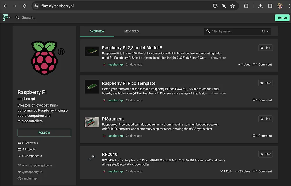
Explore our Featured Projects page to discover more Raspberry Pi projects and fresh ideas that will jump-start your next hardware prototype.
{{upsell-project}}
What Is the RP2350 A4 Stepping?
The RP2350 A4 stepping is the latest iteration of Raspberry Pi's powerful dual-core MCU, designed to correct significant hardware and security issues identified in earlier versions (particularly the A2 stepping). This update provides comprehensive improvements, delivering both enhanced security and optimized hardware performance, making it a must-have upgrade for serious developers and embedded systems designers alike.
If you're connecting the RP2350 to retro computing hardware, there's good news: after extensive testing, the RP2350 is now officially 5V tolerant!
{{underline}}
Can My Current Pico Projects Run on the New A4 Stepping?
Absolutely! Because A4 is a pin-compatible, drop-in replacement, your existing Pico designs work right away, often with nothing more than a rebuild on the latest SDK. Here are four examples you can migrate today:
- Pico Smart Automation Controller – A DIY home-automation hub that enables intelligent control for sensors, relays, and devices.
- Pico Macro Keyboard – A customizable USB HID keypad a.k.a macro pad built using the Raspberry Pi Pico 2.
- Avocaudio – Tiny Community Audio Board – A tinyML board designed for extensive audio data collection across various tinyML applications.
- Raspberry Pi Pico 2 Shield Template – A ready-made “shield” PCB that mirrors the exact footprint and pin order of the Pico 2, much like an Arduino shield.
{{upsell-project}}
{{underline}}
How Can I Tell If I Have the A2 or A4 Stepping?
You can identify the stepping version from the marking on the top surface of the chip, as illustrated below.
{{underline}}
Do Pinouts Change with the RP2350 A4 Stepping?
No, great news for hardware engineers! The pin configuration and layout of the RP2350 A4 stepping remain identical to earlier versions, making it a perfect drop-in replacement. You can upgrade existing hardware designs without any modifications to your PCB layouts.
Below, I've included a detailed pinout mapping for quick reference.
GPIO Pins
| Name | QFN-60 | QFN-80 | Type | Power Domain | Description |
| :--- | :---: | :---: | :--- | :--- | :---: |
| GPIO0 | 2 | 77 | Digital IO (FT) | IOVDD | User IO |
| GPIO1 | 3 | 78 | Digital IO (FT) | IOVDD | User IO |
| GPIO2 | 4 | 79 | Digital IO (FT) | IOVDD | User IO |
| GPIO3 | 5 | 80 | Digital IO (FT) | IOVDD | User IO |
| GPIO4 | 7 | 1 | Digital IO (FT) | IOVDD | User IO |
| GPIO5 | 8 | 2 | Digital IO (FT) | IOVDD | User IO |
| GPIO6 | 9 | 3 | Digital IO (FT) | IOVDD | User IO |
| GPIO7 | 10 | 4 | Digital IO (FT) | IOVDD | User IO |
| GPIO8 | 12 | 6 | Digital IO (FT) | IOVDD | User IO |
| GPIO9 | 13 | 7 | Digital IO (FT) | IOVDD | User IO |
| GPIO10 | 14 | 8 | Digital IO (FT) | IOVDD | User IO |
| GPIO11 | 15 | 9 | Digital IO (FT) | IOVDD | User IO |
| GPIO12 | 16 | 11 | Digital IO (FT) | IOVDD | User IO |
| GPIO13 | 17 | 12 | Digital IO (FT) | IOVDD | User IO |
| GPIO14 | 18 | 13 | Digital IO (FT) | IOVDD | User IO |
| GPIO15 | 19 | 14 | Digital IO (FT) | IOVDD | User IO |
| GPIO16 | 27 | 16 | Digital IO (FT) | IOVDD | User IO |
| GPIO17 | 28 | 17 | Digital IO (FT) | IOVDD | User IO |
| GPIO18 | 29 | 18 | Digital IO (FT) | IOVDD | User IO |
| GPIO19 | 31 | 19 | Digital IO (FT) | IOVDD | User IO |
| GPIO20 | 32 | 20 | Digital IO (FT) | IOVDD | User IO |
| GPIO21 | 33 | 21 | Digital IO (FT) | IOVDD | User IO |
| GPIO22 | 34 | 22 | Digital IO (FT) | IOVDD | User IO |
| GPIO23 | 35 | 23 | Digital IO (FT) | IOVDD | User IO |
| GPIO24 | 36 | 25 | Digital IO (FT) | IOVDD | User IO |
| GPIO25 | 37 | 26 | Digital IO (FT) | IOVDD | User IO |
| GPIO26_ADC0 | 40 | | Digital IO / Analog | IOVDD / ADC_AVDD | User IO or ADC input |
| GPIO27_ADC1 | 41 | | Digital IO / Analog | IOVDD / ADC_AVDD | User IO or ADC input |
| GPIO28_ADC2 | 42 | | Digital IO / Analog | IOVDD / ADC_AVDD | User IO or ADC input |
| GPIO29_ADC3 | 43 | | Digital IO / Analog | IOVDD / ADC_AVDD | User IO or ADC input |
| GPIO26 | | 27 | Digital IO (FT) | IOVDD | User IO |
| GPIO27 | | 28 | Digital IO (FT) | IOVDD | User IO |
| GPIO28 | | 36 | Digital IO (FT) | IOVDD | User IO |
| GPIO29 | | 37 | Digital IO (FT) | IOVDD | User IO |
| GPIO30 | | 38 | Digital IO (FT) | IOVDD | User IO |
| GPIO31 | | 39 | Digital IO (FT) | IOVDD | User IO |
| GPIO32 | | 40 | Digital IO (FT) | IOVDD | User IO |
| GPIO33 | | 42 | Digital IO (FT) | IOVDD | User IO |
| GPIO34 | | 43 | Digital IO (FT) | IOVDD | User IO |
| GPIO35 | | 44 | Digital IO (FT) | IOVDD | User IO |
| GPIO36 | | 45 | Digital IO (FT) | IOVDD | User IO |
| GPIO37 | | 46 | Digital IO (FT) | IOVDD | User IO |
| GPIO38 | | 47 | Digital IO (FT) | IOVDD | User IO |
| GPIO39 | | 48 | Digital IO (FT) | IOVDD | User IO |
| GPIO40_ADC0 | | 49 | Digital IO / Analog | IOVDD / ADC_AVDD | User IO or ADC input |
| GPIO41_ADC1 | | 52 | Digital IO / Analog | IOVDD / ADC_AVDD | User IO or ADC input |
| GPIO42_ADC2 | | 53 | Digital IO / Analog | IOVDD / ADC_AVDD | User IO or ADC input |
| GPIO43_ADC3 | | 54 | Digital IO / Analog | IOVDD / ADC_AVDD | User IO or ADC input |
| GPIO44_ADC4 | | 55 | Digital IO / Analog | IOVDD / ADC_AVDD | User IO or ADC input |
| GPIO45_ADC5 | | 56 | Digital IO / Analog | IOVDD / ADC_AVDD | User IO or ADC input |
| GPIO46_ADC6 | | 57 | Digital IO / Analog | IOVDD / ADC_AVDD | User IO or ADC input |
| GPIO47_ADC7 | | 58 | Digital IO / Analog | IOVDD / ADC_AVDD | User IO or ADC input |
QSPI Pins
| Name | QFN-60 | QFN-80 | Type | Power Domain | Reset | Description |
| :--- | :---: | :---: | :--- | :--- | :---: | :--- |
| QSPI_SD3 | 55 | 70 | Digital IO | QSPI_IOVDD | Pull-Up | QSPI data |
| QSPI_SCLK | 56 | 71 | Digital IO | QSPI_IOVDD | Pull-Down | QSPI clock |
| QSPI_SD0 | 57 | 72 | Digital IO | QSPI_IOVDD | Pull-Down | QSPI data |
| QSPI_SD2 | 58 | 73 | Digital IO | QSPI_IOVDD | Pull-Up | QSPI data |
| QSPI_SD1 | 59 | 74 | Digital IO | QSPI_IOVDD | Pull-Down | QSPI data |
| QSPI_SS | 60 | 75 | Digital IO | QSPI_IOVDD | Pull-Up | QSPI chip select / USB BOOTSEL |
Crystal Oscillator Pins
| Name | QFN-60 | QFN-80 | Type | Power Domain | Description |
| :--- | :---: | :---: | :--- | :--- | :--- |
| XIN | 21 | 30 | Analogue (XOSC) | IOVDD | Crystal oscillator; XIN may also be driven by a square-wave source |
| XOUT | 22 | 31 | Analogue (XOSC) | IOVDD | Crystal oscillator |
Misc Pins
| Name | QFN-60 | QFN-80 | Type | Power Domain | Reset | Description |
| :--- | :---: | :---: | :--- | :--- | :---: | :--- |
| RUN | 26 | 35 | Digital In (FT) | IOVDD | Pull-Up | Chip enable / reset_n |
| SWCLK | 24 | 33 | Digital In (FT) | IOVDD | Pull-Up | Serial Wire Debug clock |
| SWDIO | 25 | 34 | Digital IO (FT) | IOVDD | Pull-Up | Serial Wire Debug data |
USB Pins
| Name | QFN-60 | QFN-80 | Type | Power Domain | Description |
| :--- | :---: | :---: | :--- | :--- | :--- |
| USB_DP | 52 | 67 | USB IO | USB_QTP_VDD | USB Data +; 27 Ω series resistor required for USB operation |
{{underline}}
What’s New in the RP2350 A4 Stepping?
This stepping addresses several critical issues and introduces highly requested features:
- GPIO Leakage Bug Fixed: Resolves the notorious RP2350 erratum 9, removing unwanted current leakage on GPIO pins. As a result, external resistors are no longer required to pull inputs low, though they may safely be retained in existing designs.
- Enhanced Security: Addresses boot ROM exploits, OTP corruption, glitch vulnerabilities, and provides hardened AES encryption for secure applications.
- Integrated Flash Versions: Introduction of RP2354A/B variants with built-in 2 MB flash, simplifying hardware design and lowering production complexity.
- Official 5V GPIO Tolerance: Easier interfacing with legacy and retro-computing hardware without needing additional level shifting.
{{underline}}
Why Does the A4 Stepping Matter to You?
- Goodbye GPIO Leakage. No more worrying about external workarounds, your designs become simpler, cheaper, and more reliable.
- Stronger Security from the Ground Up. Hardened security improvements protect your products from known vulnerabilities, ensuring safer deployments, particularly important in IoT, industrial, and sensitive embedded projects.
- Simplified Hardware Design. The RP2354 integrated-flash variant significantly reduces design complexity, saving PCB space and manufacturing costs.
- Wider Compatibility. Official support for 5 V GPIO levels unlocks compatibility with more devices, sensors, and legacy systems without extra complexity.
{{underline}}
Will the A2 stepping be discontinued?
Raspberry Pi already stopped manufacturing the A2 stepping, shifted all production exclusively to A4, and removed remaining A2 inventory from distribution channels. The A4 stepping is a direct, drop-in replacement for A2, so you shouldn't encounter any issues transitioning to the newer version.
{{underline}}
How Can You Upgrade to the RP2350 A4 Stepping?
Follow these simple steps to leverage the power of RP2350 A4 in your Raspberry Pi Pico projects:
- Update your Pico SDK to version 2.1.0 or newer (recommended: 2.2.0).
- Rebuild your firmware using the latest SDK to ensure compatibility and utilize new security features.
- Switch to RP2350 A4 stepping hardware fully compatible with existing designs but with improved security and reliability.
{{underline}}
Availability and Pricing
- RP2350A/B A4 Stepping: Now widely available through official Raspberry Pi distributors.
- RP2354 Integrated Flash Variants: Available soon at around $1.30 to $1.40 per chip, simplifying your designs and saving costs.
{{underline}}
Final Thoughts
The RP2350 A4 stepping significantly upgrades the potential of Raspberry Pi Pico-based designs. Enhanced security, hardware reliability, simpler designs, and broad compatibility make this stepping a turning point for professional and hobbyist projects alike.
Explore our Featured Projects page to discover more Raspberry Pi projects and fresh ideas that will jump-start your next hardware prototype.
{{upsell-project}}