November 7, 2025
What Makes a Perfect PCB Design Prompt
Share
BuildWithFlux


Here’s a practical guide to writing prompts that get quality results from Flux. We’ll talk about the anatomy of a good prompt and how you can use different LLMs to come up with a great prompt.
Models behave like fast, literal collaborators. They do best when you hand them the same things you’d give a new teammate: context, constraints, and a definition of “done.” OpenAI, Anthropic, and Microsoft all emphasize the same fundamentals; be specific, provide context and examples, and iterate because models respond measurably better to concrete instructions than vague goals.
For hardware, that specificity translates into;
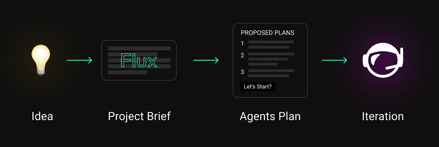
PCB design is now starting the same way, with a sentence that sets direction. The right workflow turns that sentence into a plan, and that plan into a real board.
A strong prompt has structure. You don’t need to overthink it — just fill in the blanks like you would for a teammate’s design request.
Once you’ve written that out, you’ll notice something: it’s the same info you’d include in a solid design doc. You’re just telling it to the AI in natural language.
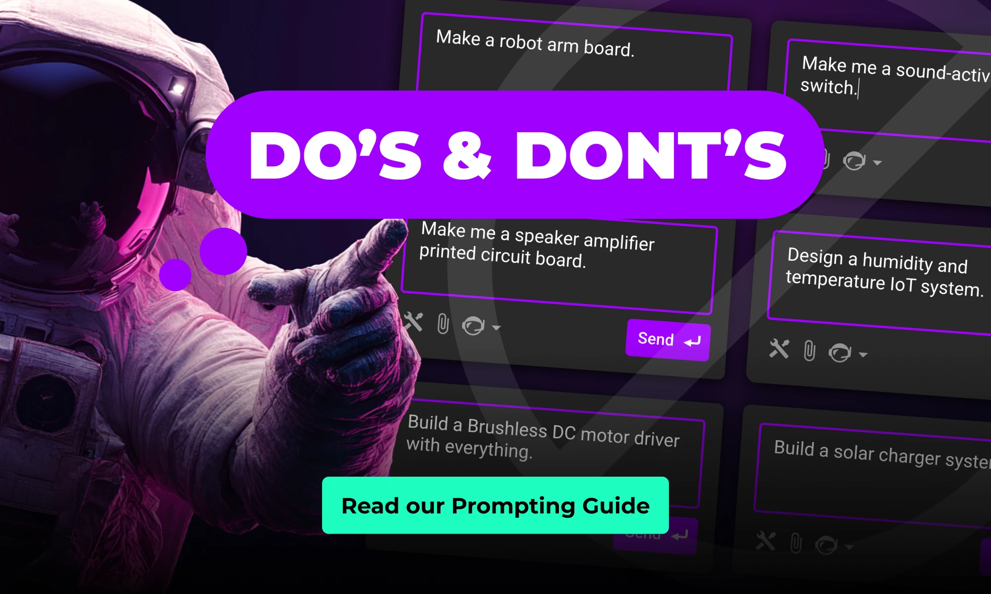
Bad
“Design a PCB to power my sensor node.”
Better
Create a compact, two-layer PCB for a battery-powered environmental sensor that can measure temperature and humidity outdoors year-round.
Functions: Step down Li-ion voltage (3.0–4.2 V) to a stable 3.3 V @ 500 mA to power an MCU and BLE module, while maintaining low noise for accurate sensor readings.
Power model: Single-cell Li-ion input with optional USB-C charging and reverse-current protection; system should support sleep modes with minimal quiescent draw.
Key constraints: Total board area ≤ 2 cm²; must use widely available components from LCSC or Mouser; prioritize efficiency (≥ 85%) and long battery life over BOM cost; all parts hand-solderable and suitable for low-volume prototyping.
Interfaces & I/O: I²C bus for sensors, UART header for debugging, JST-PH connector for the battery, and test points for power rails and signal lines.
Replace the bracketed parts, and keep it as one block.
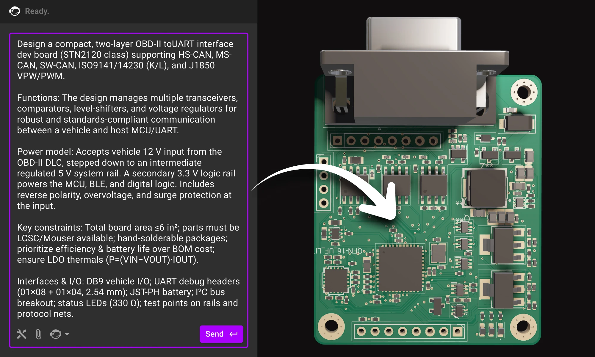
Below is a single-block prompt example for an enterprise-style project. Use the structure and adapt the content.
OzCorp’s building a robotic arm for its Kitchen Independence line—assistive gear to help folks with limited mobility cook safely. It’ll live near stovetops, inside semi-sealed enclosures, and handle risky, high-precision tasks. We need a v1 board for early testing—tight stack, safe motion, easy to iterate.
Board should be quiet, cleanable, fault-tolerant, and built with safety-first motor control. Design for real-world abuse, not just the bench.
Requirements:
* Thermal: Run clean near 70°C, layout ready for passive shielding.
* Ingress: Tolerate steam/oil, avoid exposed headers, semi-wipeable.
* EMI: Survive near induction tops; solid filtering and layout.
* Motors: Drive 4–6 steppers or BLDCs w/ encoders, quiet + smooth.
* IO: Temp + proximity sensors; USB-C or UART; room for add-ons.
Primary input will be a 24 V DC external supply—off-the-shelf medical-grade adapter. Budget ~5 A peak, ~2 A continuous for everything. Motors are 24 V BLDCs with integrated drivers, so we don’t need separate gate drive rails.
Rails we’ll need:
* 24 V passthrough for motors
* 5 V rail for sensors, logic level translators, and E-stop handling
* 3.3 V clean rail for MCU and digital IO
* 2.8 V, 1.8 V and 2.3 V analog-only rails for the camera
* No additional rails, however, keep layout flexibility in mind in case we add additional sensing later.
No galvanic isolation needed between motor and logic domains in this rev—common ground is fine as long as noise coupling is controlled. Just prioritize good filtering and separation in the layout.
We’re targeting a higher-end embedded MCU—something with enough headroom for real-time motor control, sensor fusion, and field updates without jumping to a full MPU. Needs to support external memory and camera input via MIPI CSI (basic CV down the line), and ideally has built-in Ethernet MAC with PoE support for hardwired installs.
We’re also dropping in a discrete Zigbee radio—most of the Kitchen Independence line will communicate over a shared Zigbee mesh for interoperability and OTA updates, so we’ll need clean SPI or UART for that interface, plus a decent RF layout budget. USB device is a must, USB host is a nice-to-have. No Linux this rev—we’re keeping it lean and RTOS-friendly.
This approach resembles a planning meeting rather than a netlist, allowing for a more comprehensive and strategic overview. By defining environment and safety considerations early, it significantly influences and shapes the overall architecture. Additionally, it outlines the rails and interfaces without prematurely committing to specific chips, providing greater flexibility. This method also leaves room for the agent to propose blocks and components that align with and satisfy the project's goals.
Once your requirements are clear, bring them to life. Paste your brief into a new project in Flux, and watch as your AI assistant turns that structured intent into a concrete starting point.
Flux’s AI agent doesn’t replace that balance; it amplifies it. When you give it clarity, it gives you momentum. When you ask better questions, it becomes a sharper collaborator.
Plan like a product team, define clearly, and let the AI handle the first draft of your design.
The future of hardware starts here, open Flux and start your next project today.
Here’s a practical guide to writing prompts that get quality results from Flux. We’ll talk about the anatomy of a good prompt and how you can use different LLMs to come up with a great prompt.
Models behave like fast, literal collaborators. They do best when you hand them the same things you’d give a new teammate: context, constraints, and a definition of “done.” OpenAI, Anthropic, and Microsoft all emphasize the same fundamentals; be specific, provide context and examples, and iterate because models respond measurably better to concrete instructions than vague goals.
For hardware, that specificity translates into;
PCB design is now starting the same way, with a sentence that sets direction. The right workflow turns that sentence into a plan, and that plan into a real board.
A strong prompt has structure. You don’t need to overthink it — just fill in the blanks like you would for a teammate’s design request.
Once you’ve written that out, you’ll notice something: it’s the same info you’d include in a solid design doc. You’re just telling it to the AI in natural language.
Bad
“Design a PCB to power my sensor node.”
Better
Create a compact, two-layer PCB for a battery-powered environmental sensor that can measure temperature and humidity outdoors year-round.
Functions: Step down Li-ion voltage (3.0–4.2 V) to a stable 3.3 V @ 500 mA to power an MCU and BLE module, while maintaining low noise for accurate sensor readings.
Power model: Single-cell Li-ion input with optional USB-C charging and reverse-current protection; system should support sleep modes with minimal quiescent draw.
Key constraints: Total board area ≤ 2 cm²; must use widely available components from LCSC or Mouser; prioritize efficiency (≥ 85%) and long battery life over BOM cost; all parts hand-solderable and suitable for low-volume prototyping.
Interfaces & I/O: I²C bus for sensors, UART header for debugging, JST-PH connector for the battery, and test points for power rails and signal lines.
Replace the bracketed parts, and keep it as one block.
Below is a single-block prompt example for an enterprise-style project. Use the structure and adapt the content.
OzCorp’s building a robotic arm for its Kitchen Independence line—assistive gear to help folks with limited mobility cook safely. It’ll live near stovetops, inside semi-sealed enclosures, and handle risky, high-precision tasks. We need a v1 board for early testing—tight stack, safe motion, easy to iterate.
Board should be quiet, cleanable, fault-tolerant, and built with safety-first motor control. Design for real-world abuse, not just the bench.
Requirements:
* Thermal: Run clean near 70°C, layout ready for passive shielding.
* Ingress: Tolerate steam/oil, avoid exposed headers, semi-wipeable.
* EMI: Survive near induction tops; solid filtering and layout.
* Motors: Drive 4–6 steppers or BLDCs w/ encoders, quiet + smooth.
* IO: Temp + proximity sensors; USB-C or UART; room for add-ons.
Primary input will be a 24 V DC external supply—off-the-shelf medical-grade adapter. Budget ~5 A peak, ~2 A continuous for everything. Motors are 24 V BLDCs with integrated drivers, so we don’t need separate gate drive rails.
Rails we’ll need:
* 24 V passthrough for motors
* 5 V rail for sensors, logic level translators, and E-stop handling
* 3.3 V clean rail for MCU and digital IO
* 2.8 V, 1.8 V and 2.3 V analog-only rails for the camera
* No additional rails, however, keep layout flexibility in mind in case we add additional sensing later.
No galvanic isolation needed between motor and logic domains in this rev—common ground is fine as long as noise coupling is controlled. Just prioritize good filtering and separation in the layout.
We’re targeting a higher-end embedded MCU—something with enough headroom for real-time motor control, sensor fusion, and field updates without jumping to a full MPU. Needs to support external memory and camera input via MIPI CSI (basic CV down the line), and ideally has built-in Ethernet MAC with PoE support for hardwired installs.
We’re also dropping in a discrete Zigbee radio—most of the Kitchen Independence line will communicate over a shared Zigbee mesh for interoperability and OTA updates, so we’ll need clean SPI or UART for that interface, plus a decent RF layout budget. USB device is a must, USB host is a nice-to-have. No Linux this rev—we’re keeping it lean and RTOS-friendly.
This approach resembles a planning meeting rather than a netlist, allowing for a more comprehensive and strategic overview. By defining environment and safety considerations early, it significantly influences and shapes the overall architecture. Additionally, it outlines the rails and interfaces without prematurely committing to specific chips, providing greater flexibility. This method also leaves room for the agent to propose blocks and components that align with and satisfy the project's goals.
Once your requirements are clear, bring them to life. Paste your brief into a new project in Flux, and watch as your AI assistant turns that structured intent into a concrete starting point.
Flux’s AI agent doesn’t replace that balance; it amplifies it. When you give it clarity, it gives you momentum. When you ask better questions, it becomes a sharper collaborator.
Plan like a product team, define clearly, and let the AI handle the first draft of your design.
The future of hardware starts here, open Flux and start your next project today.


This guide shows how to collaborate with Flux at the schematic stage. You’ll learn how to describe your intent clearly, guide the AI through design decisions, and review results so each iteration gets smarter.

Designing an AI pin would normally take months, but in this project, we did it in hours. In our step-by-step guide, you'll see how Flux can accelerate your design process and bring your AI pin project to life.

Discover how AI revolutionizes functional testing for PCB design. Learn to create comprehensive test plans faster with Flux Copilot, accelerating debugging processes and improving product quality.

Flux moves from one-off actions to executing multi-step workflows including researching parts, creating schematic designs, placing and routing, and running checks. Think of Flux as a capable intern — fast, explainable, and eager to learn, but still needing oversight and occasional help.

Imagine designing a PCB in a third less time than you're used to - that's the power of Flux Copilot's new upgrade, allowing it to wire components together for you. In this tutorial, we'll walk you through the important workflows and example prompts to help you design a Raspberry-Pi-Pico-like board in 20 minutes.

Imagine a future where your most complex PCB design challenges are met with an intelligent AI assistant, capable of handling everything from component selection to compliance checks. Read on to discover how Copilot, embedded within the Flux platform, is turning this vision into a reality, liberating electrical engineers to focus on what truly matters: innovation.
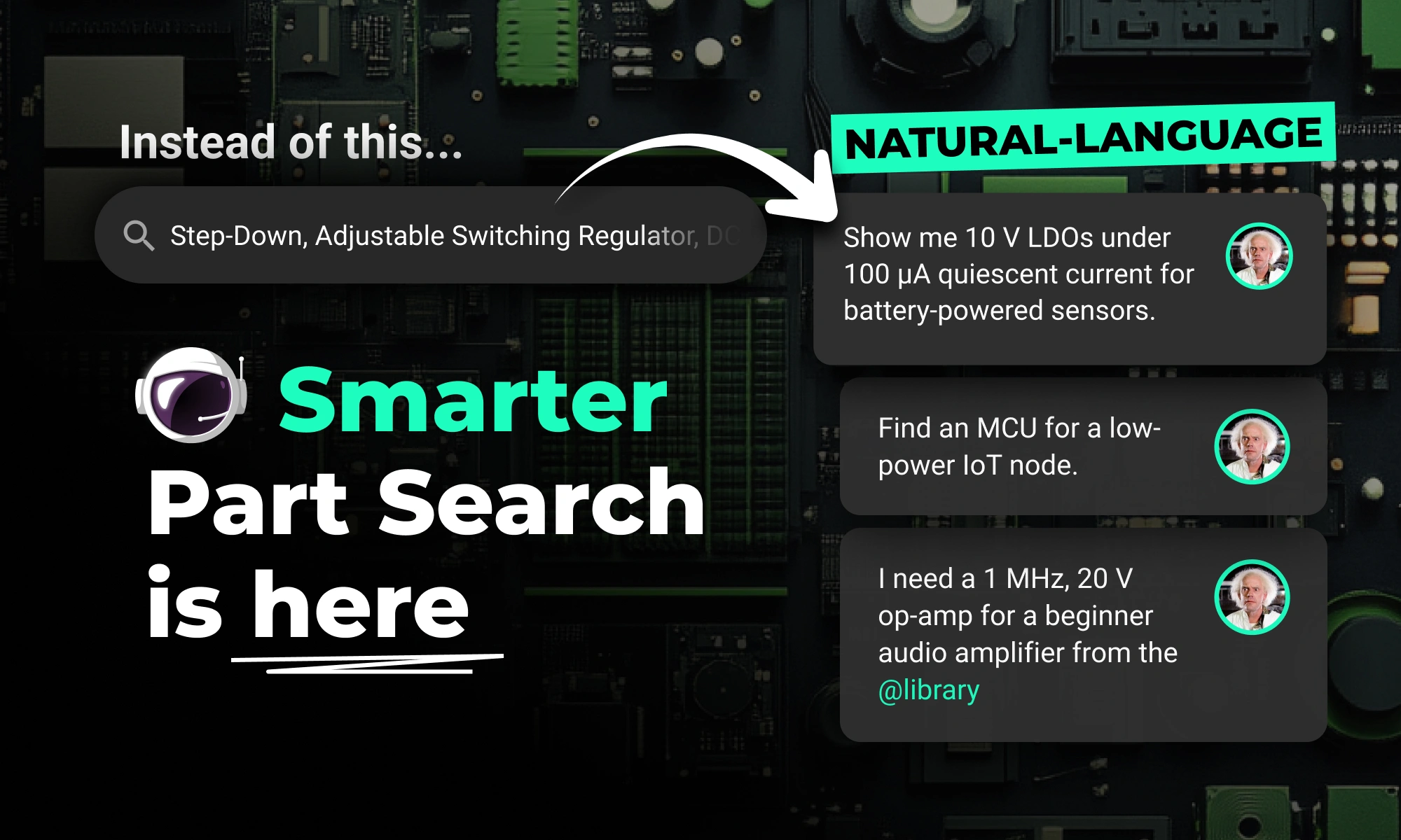
Flux Copilot’s new AI-powered part search makes finding and placing components faster and easier using natural language. It eliminates tool-switching and datasheet overload. This streamlines your PCB design workflow.

Discover how CAD Librarians can leverage Flux’s key capabilities—AI Part Imports, Component Updates, Live Pricing, and JEP30 Export—each tailored to meet the specific demands of maintaining PCB libraries.

Whether you’re routing high-speed buses, fine-tuning antennas, or laying out clean RF filters, sharp 90º or even 45º angles can be a serious bottleneck. Now, you can create precisely curved elbows across entire nets—or dial them in trace by trace—with full control over radius, inheritance, and overrides.

Flux Copilot helps your team tackle the complexities of PCB cost optimization, identifying hidden savings and providing engineers with actionable insights to streamline design processes and reduce costs.

This month, we’re rolling out major upgrades to Flux Copilot’s reasoning, transparency, and layout performance—plus some crucial fixes and a big leap in modular design reliability.
This blog breaks down the key tradeoffs between prototyping and production-ready electrical engineering, exploring how power management, RF design, PCB layout, and optimization strategies evolve from flexible, modular designs to efficient, manufacturable products.