AI Auto Layout’s Winter Update delivers cleaner, more human-like routing with faster, more reliable results. It handles most of the routing workload so you can focus on the critical parts of your PCB design.
Open Flux now, switch Copilot to “Next-gen” and see how it handles your next design challenge. The sooner you try it, the more your feedback can shape the next leap in AI-powered hardware design.
In the right scenarios, it’s already delivering sharper reasoning, smarter reviews, and more accurate design decisions than anything we’ve shipped before. We wanted to get it into your hands immediately so you can explore what’s possible alongside us. It’s early, it’s raw, and we want you to push it. Break it. Tell us where it shines.
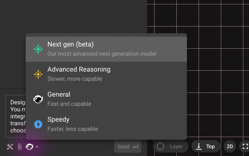
You can start using it right away. Open any project in Flux and launch Copilot. Click the model dropdown at the top of the chat panel, select “Next-gen” and then give it a real challenge. Some great starter prompts to see its strengths include:
“Perform a top-to-bottom schematic review for correctness, completeness, and robustness. Assess power, clocks/resets, signal interfaces, analog paths, protection, and passive choices.”
“Replace all low-stock parts with alternatives that meet the same constraints.”
{{try-gpt5}}
The upgrade isn’t just that GPT-5 is a newer model. It brings a different caliber of intelligence to Copilot:
These improvements land harder in Flux because Copilot already has deep, live context on your design—down to parts, pins, nets, properties, constraints, and stackups—so reinforcement models and LLMs can work side-by-side from the canvas up to system architecture. And because Flux is built for agentic workflows—stepwise actions, constraint-aware edits, and iterative design loops right where you work—GPT-5 isn’t starting from scratch; it applies improved reasoning directly to your schematic or layout. Layered on top is a knowledge base of industry best practices and embedded design/process checks, so your AI partner starts from seasoned experience and turns that context into answers that are immediately relevant and actionable.
{{underline}}
In just 48 hours of testing, we saw moments that made us stop and say, “This is new.”
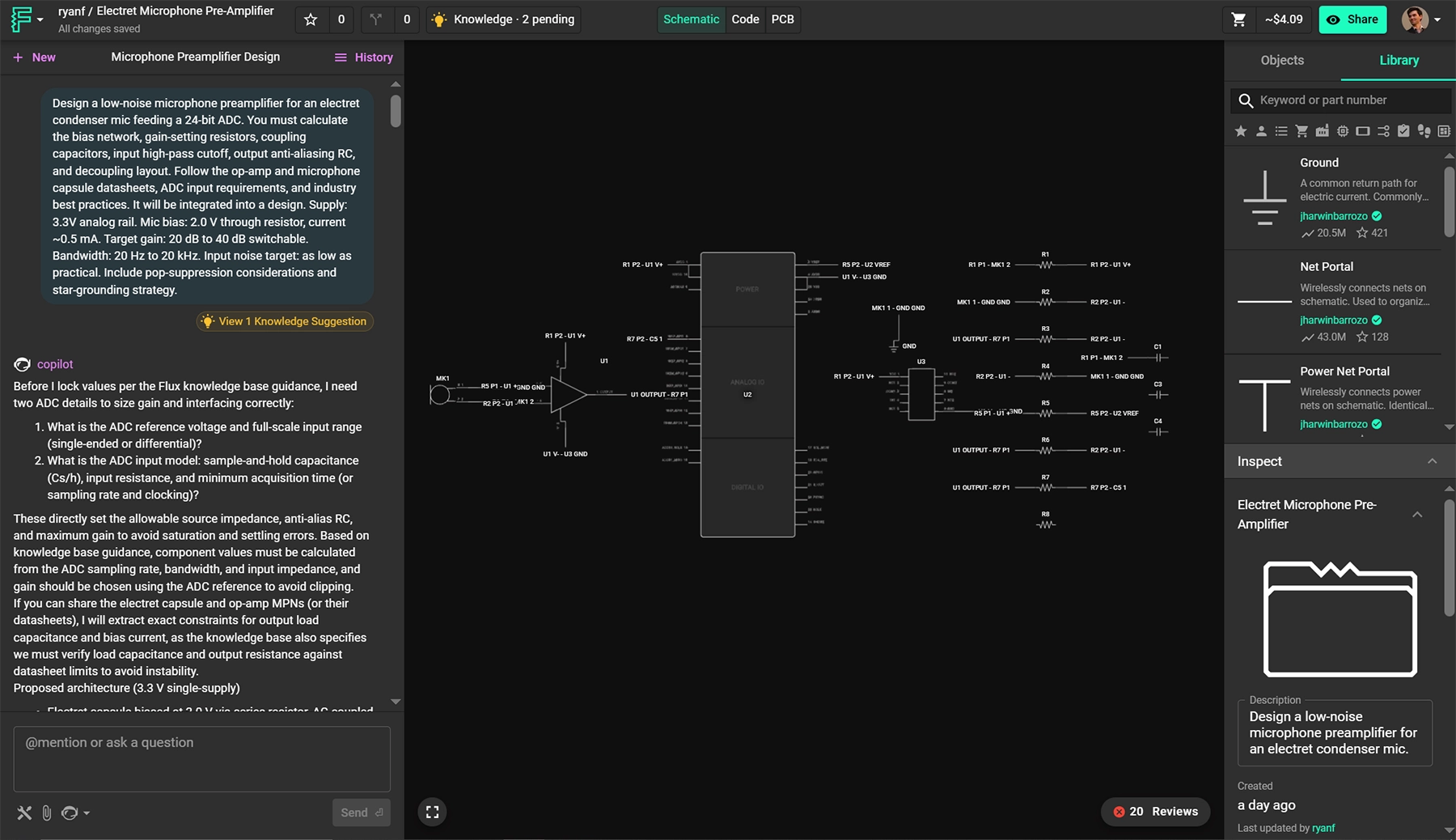
Design a low-noise microphone preamplifier for an electret condenser mic feeding a 24-bit ADC. You must calculate the bias network, gain-setting resistors, coupling capacitors, input high-pass cutoff, output anti-aliasing RC, and decoupling layout. Follow the op-amp and microphone capsule datasheets, ADC input requirements, and industry best practices. It will be integrated into a design. Supply: 3.3V analog rail. Mic bias: 2.0 V through resistor, current ~0.5 mA. Target gain: 20 dB to 40 dB switchable. Bandwidth: 20 Hz to 20 kHz. Input noise target: as low as practical. Include pop-suppression considerations and star-grounding strategy.
{{copy-the-prompt}}
In this case Flux took a plain-English prompt and produced a full low-noise mic preamp to a 24-bit ADC—calculating the right bias, gain, and filter values, choosing real parts, then placing and wiring the entire block with decoupling, VCM bias, and star-ground best practices. It even audited itself (fixed missed ties, made gain legs switchable). The result is a ready-to-review schematic 80% away from layout built end-to-end—complex, competent, and fast.
{{underline}}
{{underline}}
Right now GPT-5 powers Copilot’s chat, but this is just the beginning. We’re already working on:
Open Flux now, switch Copilot to “Next-gen” and see how it handles your next design challenge. The sooner you try it, the more your feedback can shape the next leap in AI-powered hardware design.
{{try-gpt5}}
This blog compares AI capabilities across Flux.ai, Altium, KiCad, and EasyEDA to answer engineers’ highest-intent questions about modern PCB design. It explains why Flux.ai currently delivers the strongest end-to-end AI workflow in the ECAD space.
The reality in 2025 is this:
Not a perfect one, not one you fully trust yet, but one that can save time on the tedious parts, catch mistakes earlier, and help you iterate from idea to prototype faster.
Across the industry, adoption is uneven. Traditional desktop ECAD tools like Altium and KiCad still treat AI as an optional plugin or an external script-driven add-on. Meanwhile, newer cloud-native platforms, most notably Flux.ai, have begun integrating AI directly into the design loop: reading datasheets, proposing schematics, suggesting parts, routing boards, and even explaining the reasoning behind design choices.
But engineers are right to be cautious. PCB design isn’t text prediction, it’s physics, constraints, standards, and consequences. A misrouted high-speed lane, wrong MOSFET footprint, or power sequencing mistake isn’t a typo; it’s a lost week, lost money, and sometimes a lost product.
This article focuses on the questions hardware engineers really ask, the practical, high-stakes ones that determine whether AI can actually save time or just create new risks. Each section breaks down how modern ECAD tools like Flux, Altium, KiCad, and EasyEDA — handle these real-world workflows.
{{underline}}
Most engineers start with vague product requirements — “battery-powered sensor,” “USB-C powered device,” “motor controller” but translating that into electrical design constraints is slow and error-prone. An AI that can read a spec and ask the same clarifying questions a junior engineer would (power budget, interfaces, sensors, EMI constraints) reduces iteration time and catches missing requirements early.
Short answer: Flux is the only ECAD that does this natively today.
Flux can interpret natural-language specs, ask clarifying questions, propose block diagrams and functional structure then it generates a detailed plan. It behaves like a junior hardware engineer thinking out loud.
Try this prompt:
Design a sub-25 × 25 mm wearable PCB with Bluetooth, an accelerometer, and on-board battery charging.
It must include a BLE SoC (OTA-capable), a low-power accelerometer with interrupt/wake, power-path + charging for a 1-cell Li-ion/LiPo, and headers/pads for programming and test.
Power: 1-cell Li-ion/LiPo with on-board charger (5 V USB input) optimized for low quiescent current.”
{{try-this-prompt-xyz}}
No native AI planning. External tools may help with ideation, but no clarifying questions.
Completely manual. You are on your own.
Has basic AI chat, but no requirements-driven design planning.
{{underline}}
In real workflows, engineers often spend hours picking components, checking footprints, wiring standard circuits, and placing obvious blocks like regulators, microcontrollers, and connectors. A capable AI that drafts these first passes while letting the engineer steer and refine, dramatically accelerates early design cycles and frees time for deep engineering decisions.
Flux currently has the most advanced AI-assisted design flow:
Altium can help with component data via Octopart, but AI doesn't generate schematics or placement.
No AI, only scripting through third-part plugins
Basic recommendations and cloud routing, but not AI-driven.
{{underline}}
Hardware teams develop their own standards over years, naming conventions, preferred footprints, power-tree structures, and layout principles. Re-teaching those rules every time a new engineer joins or every time you start a new board is one of the biggest sources of avoidable friction in PCB workflows.
Flux solves this with its Knowledge Base, which allows engineers to store reusable electrical engineering “knowledge chunks” the AI can reference during design. Unlike static templates, the Knowledge Base includes:
Flux doesn’t just store these rules, it applies them automatically when generating schematics, naming nets or choosing footprints strategies. It’s the first ECAD tool where your internal engineering standards become a living and reusable knowledge system.
These tools rely on templates, scripts, or third-party plugins but none provide persistent, context-aware AI learning or automatic implementation of company standards.
{{underline}}
Engineers need to trust routing, and part choices, especially when they affect signal integrity, EMI, power delivery, or thermal behavior. Having an AI that can justify decisions (“this cap is here to shorten loop inductance,” “this MOSFET variant reduces cost with identical performance”) closes the trust gap and makes AI-driven design actually usable in production workflows.
One of the biggest differentiators: Flux gives clear natural-language reasoning.It explains why something routed, or chosen.
No explainable AI features exist.
{{underline}}
Most commercial products aren’t 12-layer high-speed monsters, they’re 2–4-layer sensor nodes, wearables, IoT modules, power converters, and mixed-signal control boards. For these designs, route quality depends far more on smart placement, clean topologies, and constraint-aware decision making than on raw high-density routing power. This is where the newest generation of AI-driven algorithms has begun outperforming classical routers.
Flux’s AI Auto-Layout represents the most human-like routing behavior available in ECAD today. With Flux’s latest update, the system doesn’t simply push traces through a maze router, it imitates how real engineers reason about routing:
For low-to-medium density boards (2–4 layers), Flux’ Auto-Layout produces results that closely resemble an experienced EE’s first-pass layout, not a mechanical maze-router output. It’s the first auto-layout system that actually looks designed, not auto generated.
Altium’s ActiveRoute remains one of the best deterministic routers on the market. It’s excellent when the designer put up so much time setting up constraints properly, but it still relies on classical algorithms rather than human-like reasoning.
FreeRouting offers reasonable results for simpler boards, but it struggles with medium-density designs or anything requiring nuanced placement strategy.
EasyEDA’s router is functional and fast for hobby-level projects, but lacks advanced constraint handling or professional-grade refinement.
{{underline}}
Even experienced engineers overlook missing pull-ups, incorrect footprints, swapped differential pairs, or bad return paths when moving fast. AI-driven review acts like a second pair of eyes that never gets tired, catching easy-to-miss issues before fabrication, when mistakes are still cheap.
Flux runs a deep AI review:
Altium, KiCad, and EasyEDA provide ERC/DRC — but no AI reasoning.
Every other tool still treats AI as a bolt-on accessory, helpful around the edges but never involved in real engineering decisions. Flux.ai takes the opposite approach: AI is embedded in the workflow from the moment you describe your product idea to the moment you’re reviewing your final layout. It asks the right questions, explains its decisions, follows your internal rules, and eliminates entire categories of tedious work that engineers have accepted for years.
This isn’t “AI for PCB design someday.” It’s the first platform where AI becomes a capable design partner today.
If you’re serious about faster iteration, fewer mistakes, and a workflow that evolves with the future of hardware development, Flux.ai is the tool that sets the new standard, and the direction the rest of the industry will be trying to catch up to.
{{try-flux-today}}
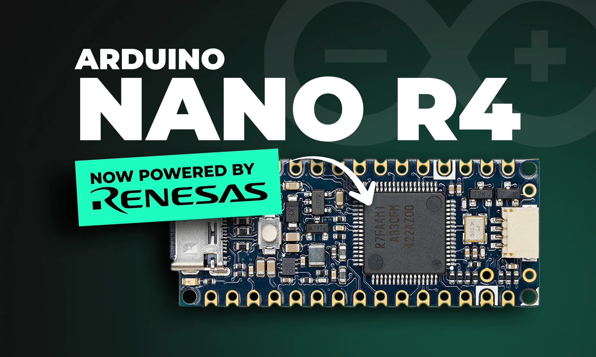
Arduino Nano R4 packs UNO R4 performance into Nano size. Learn specs, standout features, and who should upgrade in this in-depth guide.
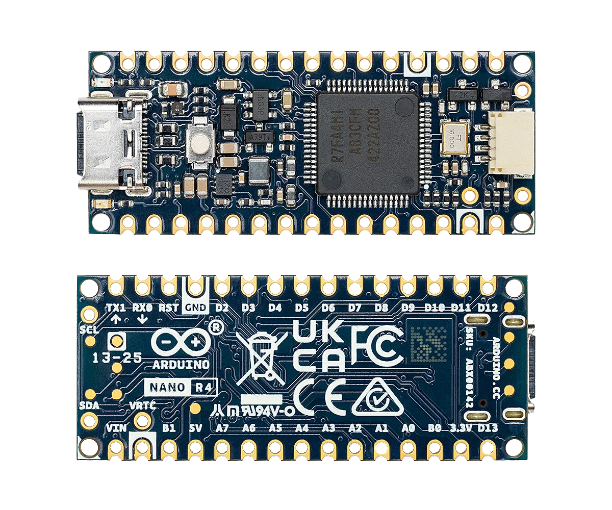
The Arduino Nano R4 is a significant upgrade to Arduino’s popular Nano line, powered by the Renesas RA4M1 microcontroller. Imagine taking the powerful brains of the Arduino UNO R4 and shrinking them into a tiny, versatile form. With a 48 MHz Arm Cortex-M4F core, 256 KB of flash storage, and integrated EEPROM, the Nano R4 provides remarkable performance in a miniature footprint.
Regardless of whether you're prototyping, building IoT projects, or designing space-conscious hardware, the Nano R4 is designed to streamline your workflow and empower your creativity.
{{underline}}
The Nano R4 offers exciting new features, making it one of Arduino’s most attractive small boards ever released:
{{underline}}
Browse the shield templates below, each pre-aligned with headers, that let hardware engineers move from concept to working prototype in record time. Choose a template, customize it to your needs, and start building.
{{upsell-project}}
{{underline}}
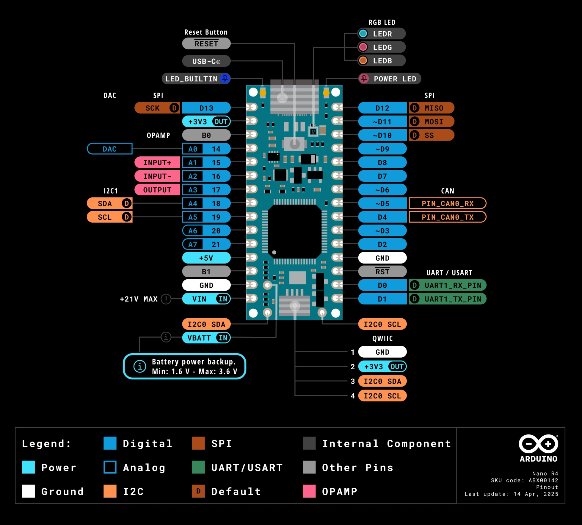
Arduino Nano R4 keeps the classic Nano pin layout, so headers, shields, and breadboard wiring stay the same. Yes, just remap the pin numbers to match the Nano R4 layout. The Nano breakout connectors pinout is shown below:
{{underline}}
Nano R4 packs high-end functionality previously reserved for larger Arduino boards into a sleek, ultra-compact form factor. This allows makers to design more sophisticated, compact IoT and wearable projects without compromising power or features.
Already using Arduino’s popular UNO R4 boards? The Nano R4 offers complete compatibility with UNO R4’s software ecosystem, meaning your existing libraries, sketches, and workflows transfer smoothly to your Nano-sized projects.
The castellated headers and single-sided components ensure easy and cost-effective manufacturing—perfect for makers looking to transition prototypes into commercial products quickly and affordably.
The integrated Qwiic connector and additional I²C lines allow effortless integration of sensors, displays, and other peripherals. Add the RTC and RGB LED, and you have a remarkably versatile board ready for endless applications.
{{underline}}
The Nano R4 meets a variety of needs:
{{underline}}
Compared to older Nano models (Nano Every or Nano 33), the Nano R4 offers substantial performance and memory improvements:
The Nano R4 brings many of the features previously only available in higher-end Arduino boards into a Nano-sized form factor.
{{underline}}
If you're currently using older Nano boards or even an Arduino UNO, here are quick reasons to make the jump to Nano R4:
{{underline}}
The Arduino Nano R4 is available in two variations:
Both versions are available directly from Arduino's online store and major electronics distributors.
{{underline}}
Arduino’s Nano R4 sets a new standard for compact, powerful, and production-friendly microcontroller boards. Whether you’re prototyping the next big IoT device or scaling your prototype for production, the Nano R4 offers the power and flexibility you need.
Visit our Featured Projects page to discover innovative Arduino builds and spark inspiration for your next big idea.
{{upsell-project}}
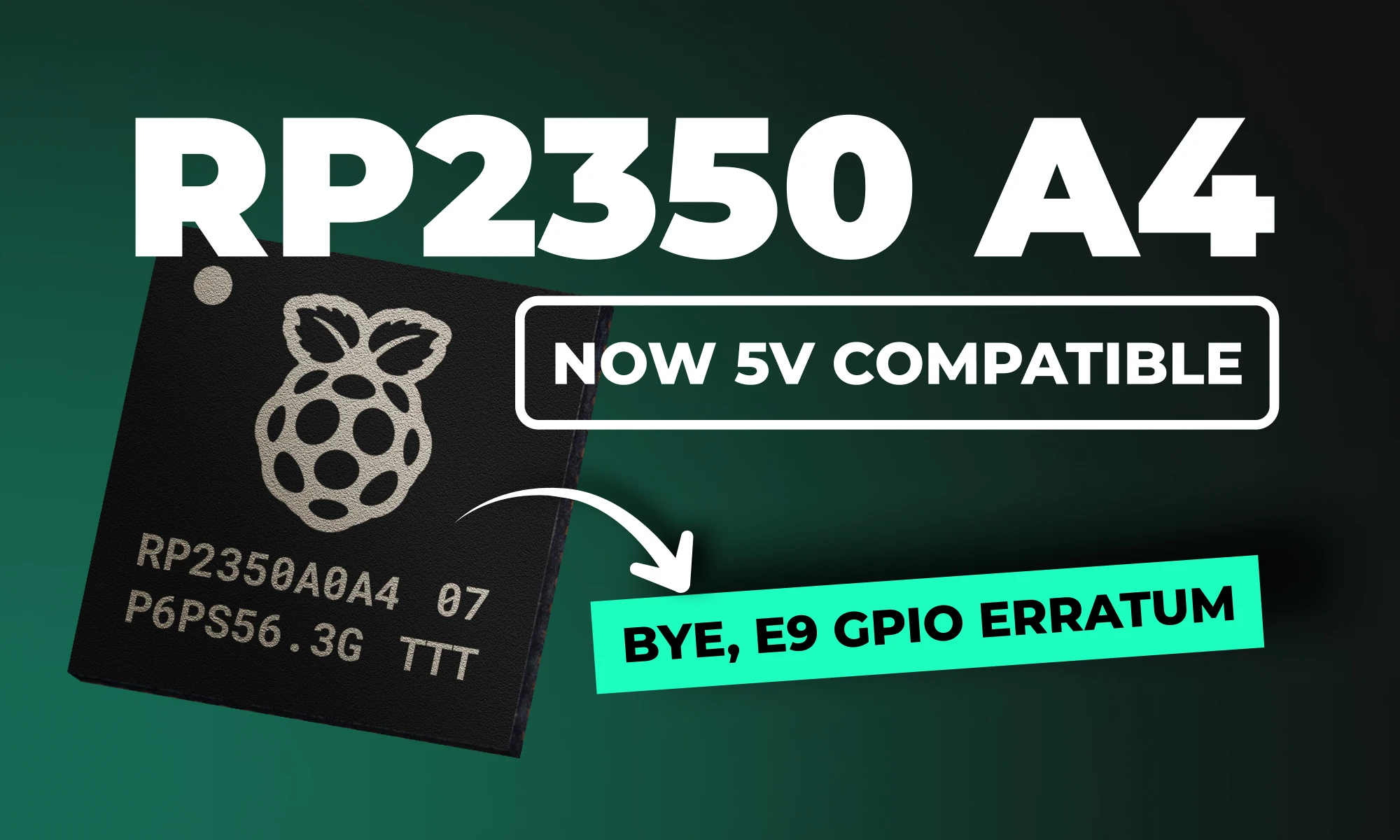
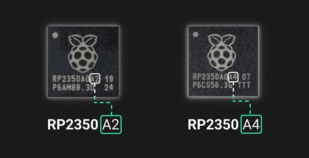
RP2350 A4 fixes GPIO bug, hardens security, adds 5 V tolerance and on-chip flash. See why every Pico project should migrate.
The RP2350 A4 stepping is the latest iteration of Raspberry Pi's powerful dual-core MCU, designed to correct significant hardware and security issues identified in earlier versions (particularly the A2 stepping). This update provides comprehensive improvements, delivering both enhanced security and optimized hardware performance, making it a must-have upgrade for serious developers and embedded systems designers alike.
If you're connecting the RP2350 to retro computing hardware, there's good news: after extensive testing, the RP2350 is now officially 5V tolerant!
{{underline}}
Absolutely! Because A4 is a pin-compatible, drop-in replacement, your existing Pico designs work right away, often with nothing more than a rebuild on the latest SDK. Here are four examples you can migrate today:
{{upsell-project}}
{{underline}}
You can identify the stepping version from the marking on the top surface of the chip, as illustrated below.
{{underline}}
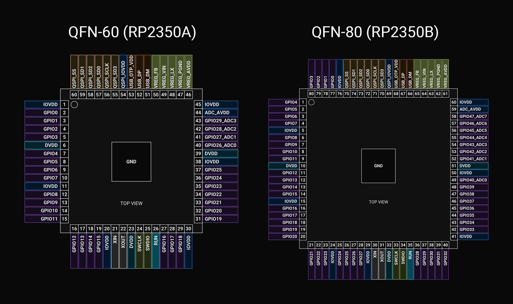
No, great news for hardware engineers! The pin configuration and layout of the RP2350 A4 stepping remain identical to earlier versions, making it a perfect drop-in replacement. You can upgrade existing hardware designs without any modifications to your PCB layouts.
Below, I've included a detailed pinout mapping for quick reference.
{{underline}}
This stepping addresses several critical issues and introduces highly requested features:
{{underline}}
{{underline}}
Raspberry Pi already stopped manufacturing the A2 stepping, shifted all production exclusively to A4, and removed remaining A2 inventory from distribution channels. The A4 stepping is a direct, drop-in replacement for A2, so you shouldn't encounter any issues transitioning to the newer version.
{{underline}}
Follow these simple steps to leverage the power of RP2350 A4 in your Raspberry Pi Pico projects:
{{underline}}
{{underline}}
The RP2350 A4 stepping significantly upgrades the potential of Raspberry Pi Pico-based designs. Enhanced security, hardware reliability, simpler designs, and broad compatibility make this stepping a turning point for professional and hobbyist projects alike.
Explore our Featured Projects page to discover more Raspberry Pi projects and fresh ideas that will jump-start your next hardware prototype.
{{upsell-project}}
Today, we’re excited to share our Summer Update to Flux AI Auto‑Layout, a collection of improvements designed to make one‑click PCB routing more reliable, transparent, and adaptable to your real‑world workflows.
This update is a set of pragmatic steps toward our vision of Auto‑Layout as your trusted routing assistant. Here's what's improved:
Auto‑Layout still works best when guided by thoughtful placement, clear net names, and rulesets—but now it’s a more predictable, collaborative partner in your design process.
Classify your nets into seven priority buckets—High Speed, Analog, Power, Medium Speed, Low Speed, Uncertain, and Ground—and Auto‑Layout will route them in that exact order. Flux will infer the Net Type of each net in your design, but you can check and change the inference by selecting a net and altering the Net Type property.
High‑speed nets go first.
Analog nets get their own quiet lanes.
Power nets find robust copper paths.
This helps ensure your most sensitive signals aren’t forced into awkward detours, delivering a draft layout that mirrors your own routing instincts.
Previous versions of Flux Auto‑Layout often scrunched traces up against neighboring pads or nets to minimize length. We’ve softened that bias so traces now favor open board areas—even if they grow a few mils longer.
Think of it as trading a few extra mils for a huge win in clarity and yield.
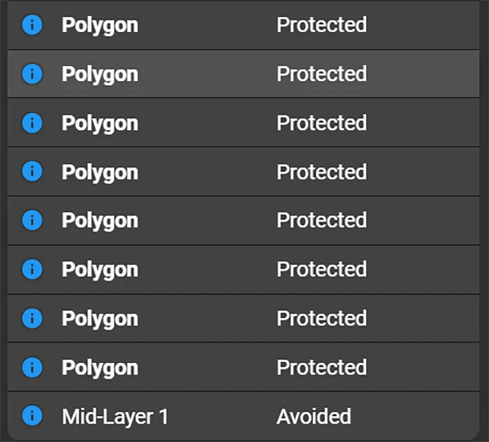
Earlier, Auto‑Layout could inadvertently slice through copper pours—especially smaller ones. Now, any polygon covering less than 10% of the board area is automatically protected from wires and vias unless you explicitly disable that rule.
Auto‑Layout shines when you guide it. Here’s a quick workflow that scales from beginners to power users:
Either way, Auto‑Layout becomes a force multiplier—not a replacement for your expertise.
This Summer Update is a milestone on our roadmap. In the coming months, expect deeper AI understanding of complex topologies, tighter integration with constraint management, and collaborative features that let teams iterate on one layout in real time.
Your feedback is the compass that guides us. Try the Summer Update today—log in, hit “Auto‑Layout”, and tell us where it shined or stumbled via in‑app feedback or our Slack channel. Together, let’s make routing the easiest part of hardware design.
In this post, we’ll show you exactly how to unlock the power of Flux Copilot for yourself: from writing rock-solid triggers to scoping entries at the project, user, and system levels.
Today, EE teams using Flux are already leveraging Knowledge Base to encode their professional know-how—things like project constraints, personal style guides, and industry-vetted best practices—directly into Copilot. In this post, we’ll show you exactly how to unlock that power for yourself: from writing rock-solid triggers to scoping entries at the project, user, and system levels.
Don’t miss out on this opportunity. Take these tips and tricks, apply them today, and watch Copilot transform from a tool into a teammate who thinks—and designs—just like you.
With Knowledge Base, we capture insights at three levels:
Let’s dive into how it works, why it matters, and—most importantly—how you can craft entries that make Copilot truly think like you.
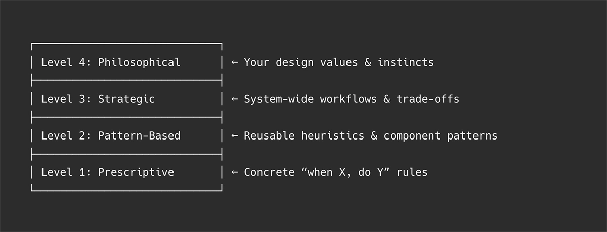
Flux Copilot’s Knowledge Base entries can be thought of at four levels—from narrow rules to high-level mindsets. When you prompt Copilot, it performs a semantic search, a search that uses sentence structure similarity to find matches , then weaves the most relevant guidance into its reasoning.
Every entry begins with a “use when” phrase. Copilot uses vector search, finding similar items in a dataset by comparing their numerical vector representations (embeddings) instead of relying on exact keyword matches, to match your prompt to the right piece of advice based on semantic similarity.
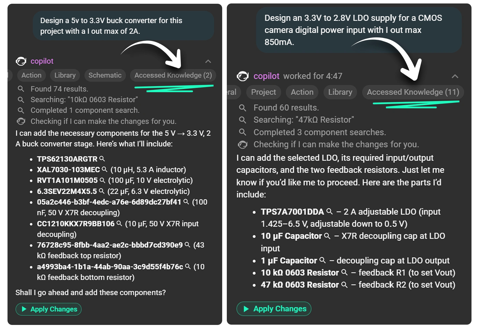
When you ask Copilot, for example, to generate a buck-converter schematic, it retrieves relevant entries—your project’s input-voltage constraint, your favorite inductor series, or a net-naming rule—and seamlessly injects that context into its response.
The “use when” is the most critical piece of any entry—it tells Copilot when to apply your guidance, based on semantic similarity, not just keywords. If this is off, your advice will never—or always—fire.
Pro Tip: After Copilot suggests a “use when,” refine it immediately. A small tweak—“for high-speed analog filters” instead of just “for filters”—can mean perfect recall instead of irrelevant noise.
Project-level entries store all the details that make your current board design one-of-a-kind. They include specific requirements (like voltage tolerances), physical or thermal constraints, chosen topology decisions, and any reference calculations you’ve performed. By capturing the reasoning behind each architectural choice, Copilot can apply context-aware guidance tailored solely to this project. This prevents generic suggestions from slipping through and keeps your design aligned with its unique specifications.
use when: selecting temperature sensitive components
content: this design is exposed to temperatures of -10 F to 110 F on a Northeastern US State yearly temperature cycle.
use when: board size constraints
content: Ensure components selected are optimized for a wearable device sized board.
use when: designing a power distribution network
content: Optimize for small size and effeciency for each power component.
User-level entries capture your personal design preferences, workflows, and preferred subcircuit patterns so that Copilot reflects how you work. They let you encode procedural steps—like your favorite LDO selection or filter-design process—directly into Copilot’s memory. With these entries, Copilot adopts your schematic conventions, part choices, and step-by-step habits, producing outputs that feel tailored and familiar. In effect, it transforms Copilot from a generic assistant into one that thinks and advises just as you would.
use when: LDO selection process
content: When selecting an LDO, follow a structured four-step workflow: screen basic parameters, filter performance (PSRR, noise), prioritize the key metric, and check optional features.
use when: filter design process
content: When formalizing filter design, begin with clear specs (ripple, f_c, f_s, attenuation) and then proceed with topology selection, component choice, simulation, and disciplined prototyping.
use when: naming nets for differential pairs
content: Prefix with SIG_DP_ or SIG_DM_ and suffix with _N/_P for polarity clarity.
use when: naming nets with series resistors
content: Add a suffix _R to the name of the incoming net to the resistor and use it for the outgoing net name.
use when: designing op-amp instrumentation amplifiers
content: Add 10 Ω series resistors on each input to decouple source capacitance.
use when: using TI SN65HVD230 CAN transceiver
content: Place 120 Ω termination resistors close to the transceiver and add 0.1 µF decoupling on VCC.
Our EE team crafts system entries with the highest rigor—so every user benefits from vetted best practices.
Note: Every word is chosen deliberately—“use when” must be as true as the “content” it triggers.
As your KB grows, keep it relevant and helpful by:
Adding your knowledge to Copilot doesn’t just make it smarter—it makes you faster, more consistent, and more confident. Open Flux Copilot, watch for that “Knowledge Suggestion” button in the response, and begin teaching your AI teammate how you design. Over time, your Knowledge Base becomes a living encyclopedia of your best practices—project by project, decision by decision.